Grant’s Tomb is off the beaten track tread by most visitors to Manhattan.
Photo source: www.timeshutter.com
Once one of the most popular attractions in New York City, today Grant’s Tomb is off the beaten track tread by most visitors to Manhattan. Constructed with the assistance of donations from 90,000 people totaling $600,000, the most money raised for a public monument at the time, the structure later suffered from neglect and fell into decline.[1] Although it stands on a prominent point of Riverside Park overlooking the Hudson River, Grant’s Tomb is hidden in plain sight, with relatively few people venturing inside the mausoleum that contains the remains of President Ulysses S. Grant and his wife, Julia Dent Grant.

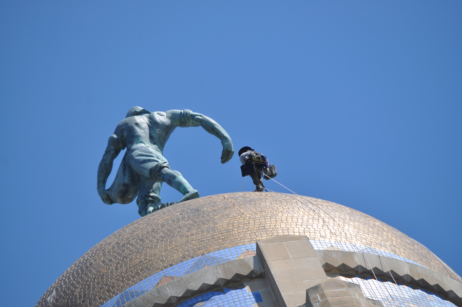
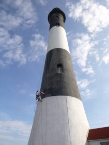
Grant’s Tomb was constructed between 1891 and 1897. Photo source: National Park Service
Grant’s Tomb was designed by New York architect John H. Duncan and constructed between 1891 and 1897. The exterior is based on the Mausoleum of Halicarnassus and the interior is modeled after the Tomb of Napoleon at Les Invalides in Paris. On the exterior, the structure consists of a square base surmounted by a conical dome with a tall, colonnaded drum level, all faced with granite. The main entry on the south side of the structure is distinguished by a wide plaza with steps leading up to a portico covering monumental bronze doors. The ground floor has a large oculus through which the sarcophagi on the floor below can be seen. Polished marble from Massachusetts is used for the interior floor surfaces and the railings, trim and dados at the walls of the ground floor and basement are clad with Italian marble. The upper areas of the interior, including four barrel vaults facing the cardinal directions of the base of the monument, the pendentives where the square base transitions to the dome, the gallery at the drum level and the coffered ceiling at the interior dome, are faced with ornamental cast plaster.
The Grant Monument Association operated Grant’s Tomb until 1959, at which time the National Park Service took over management control and the site was designated as General Grant National Memorial. From the 1970s to the early 1990s, visitors who ventured to Grant’s Tomb would find the granite walls of the monument covered with graffiti, the glass in the windows broken and the site in an overall state of disrepair. Finally, faced with public criticism and a threat from the Illinois state legislature to move the remains of the Grants to their state, the federal government undertook much-needed repairs. Following the restoration effort, the monument was re-dedicated on April 27, 1997.
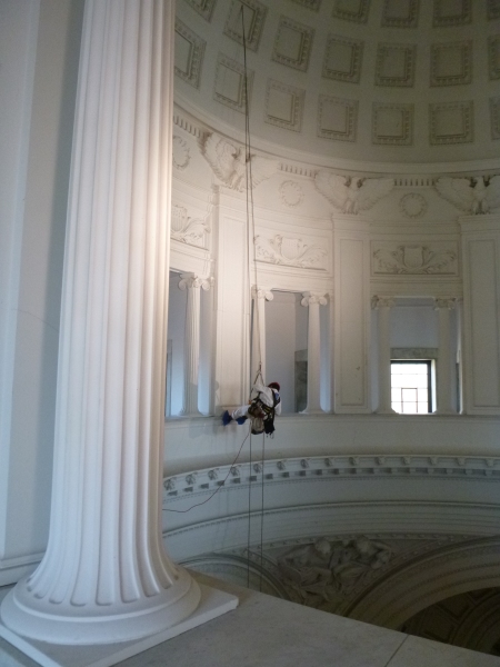
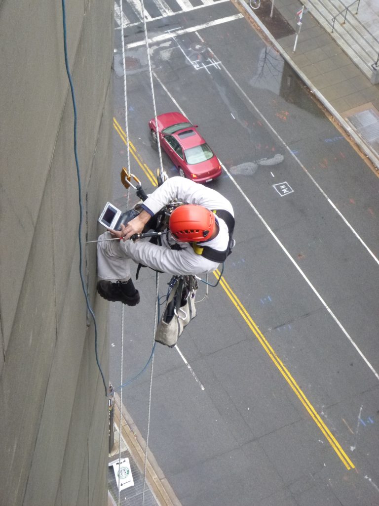
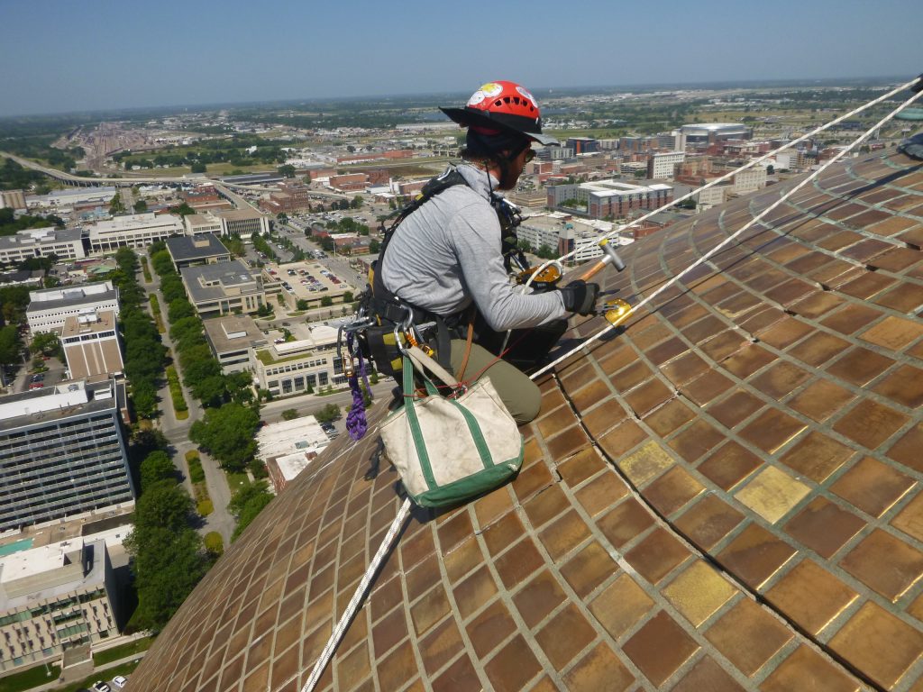
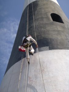
Hands-on investigation of the plaster pilasters. Photo by Vertical Access.
As part of a site inspection of the General Grant National Memorial performed in 2012, National Park Service staff identified areas of cracking at the interior plaster at the drum level of the rotunda. Some of the plaster at the pilasters at this area appeared detached. The National Park Service requested the services of Vertical Access to perform a hands-on investigation of the plaster pilasters to better understand the causes of the cracks and determine whether the current condition presented an immediate public safety hazard.
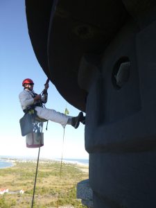
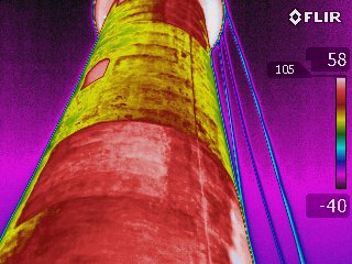
As part of the investigation of the interior plaster, Vertical Access utilized several non-destructive and diagnostic tools. As a first step, VA laid out the location of rigging holes in the coffered ceiling for the industrial rope access approach. To locate the first rigging hole at the ceiling, a self-leveling laser level positioned on the ground floor was first used to establish the plumb line for the drop ropes in front of one of the pilasters. To confirm which coffer was in line with the center of the pilaster when viewed from the attic side of the ceiling, the unfinished attic side of the coffer was warmed with a heat gun and the finished interior side was viewed with an infrared camera from the ground level.
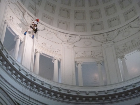
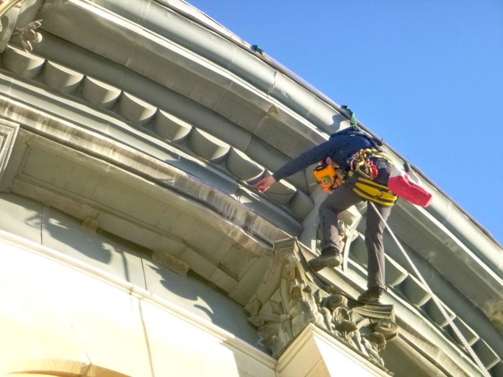
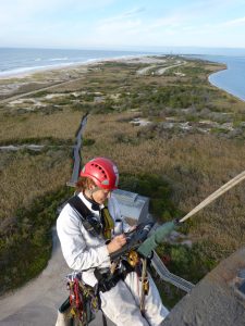
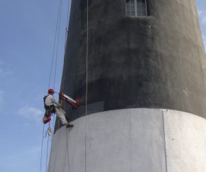
Conditions were documented using annotated drawings, still photography and video. Photo by Vertical Access.
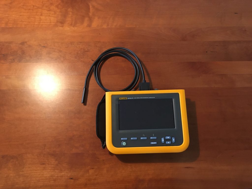
Once drop ropes were in place, Vertical Access technicians performed the hands-on investigation of the plaster pilasters, using diagnostic tools to better understand the construction of the pilasters and further investigate conditions of deterioration observed at the face of the pilasters. A wall tie locator and rigid tube borescopes with a 0° (straight ahead) and 90° (right angle) direction of view as well as a 36”-long flexible tube borescope were employed during the investigation. A video camera attached to the borescope unit provided recorded documentation of the subsurface conditions. The cast plaster sections of the pilasters appear to be attached to the brick back-up structure with wood blocking. Metal elements including wire ties and nails appear to have been used but no evidence of straps or anchors into the plaster was found.
Conditions identified during the hands-on and close visual examination of the interior plaster were documented using annotated drawings, still photography and video. At the conclusion of the investigation, Vertical Access installed crack monitors at two different pilasters. Although the condition of the interior plaster does not represent an immediate threat to public safety, the crack monitors will be used to help determine whether the cracks observed are active.
* From Groucho Marx in the game show “You Bet Your Life”. The correct answer is no one, since Ulysses S. Grant and his wife Julia are entombed but not buried in the memorial.
[1] Keister, Douglas. Stories in Stone New York: A Field Guide to New York City Area Cemeteries & their Residents: Layton, UT: Gibbs Smith, 2011. Page 142.